
1 By Making The Substitution K N In 5 22 Show That Y N Can Also Be Expressed In The 2297870
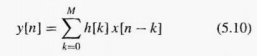
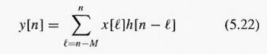
1. By making the substitution k = n – ![]() in (5.22), show that y[n] can also be expressed in the same form as (5.10),
in (5.22), show that y[n] can also be expressed in the same form as (5.10),
![]()
2. Determine the impulse response h[n] of the 51-point causal running avenger and determine the impulse response ![]() for the 51-point centralized running avenger.
for the 51-point centralized running avenger.
P-5.1 If the impulse response h[tt I of an FIR filter is h[n] = S[n – I] – 281n – 41 write the difference equation for the FIR filter. P-5.2 Evaluate the “running” avenge for the unit-step input signal, i.e., (a) Make a plot of uln] before working out the answer for yin I. (b) Now compute the numerical values of yin] over the time interval -5 0.
P-5.3 A linear time-invariant system is described by the difference equation (a) When the input to this system is Compute the values of An], over the index range 0
(b) For the previous part. plot both x[n] and yin I. (c) Determine the response of this system to a unit impulse input; i.e., find the output y[n J = h[n] when the input is x [n] = S[n I. Plot WI as a function of n.
P-5.4 A linear time-invariant system is described by the difference equation (a) Draw the implementation of this system as a block diagram in direct form. (12) Give the implementation as a block diagram in transposed direct form. p-5.5 Consider a system defined by (a) Suppose that the input x[n] is nonzero only for 0
(a) Make a plot of stint (b) We can use the unit-step sequence to represent other sequences that are zero fora
(c) The L-point running avenge is defined as For the input sequence x[nI = (0.5)”u[n), compute the numerical value of yin) over the index range -5 0. In doing so, you may have use for the formula: P-5.7 Answer the following questions about the time-domain response of FIR digital filters: When tested with an input signal that is an impulse, x[nl = Sin), the observed output from the filter is the signal h[n) shown in Fig. P-5.7. Determine the filter coefficients (h) of the difference equation for the FIR filter.
P-5.8 If the filter coefficients of an FIR system are (141 = 113. -13, 13) and the input signal is determine the output signal yin] for all n. Give your answer a 2 • either a plot or a formula. P-5.9 For each of the following systems. determine whether or not the system is ( I) linear, (2) time-invariant, and (3) causal. P-5.10 Suppose that S is a linear, time-invariant system whose exact form is unknown. It is tested by running some inputs into the system, and then observing the output signals. Suppose that the following input-output pairs are the result of the tests: (a) Make a plot of the signal: (b) Use linearity and time invariance to find the output of the system when the input is P-5.11 A linear time-invariant system has impulse response
kin) = 38ln) – 28[n – 1] + 4Sin – 21+ Sin -4] (a) Draw the implementation of this system as a block diagram in direct form. (b) Give the implementation as a block diagram in transposed direct form. P-512 For a particular LTI system, when the input is the unit step, xi [n] = u[n), the corresponding output is Determine the output when the input to the LTI system is .x.2[n] = 3u[nI – 2u[n – 4]. Give your answer as a formula expressing y2[11] in terms of known sequences, or give a list of values for -co
P-5.13 For the FIR filter yin) = x[n)- ax[n – determine the output signal for two similar cases. (a) The input signal is x[n) = a” urn). (b) The input signal is x[n] = a” (u[n] – u[n – 10)).
P-5.14 One form of the deconvolution process starts with the output signal and the filter's impulse response, from which it should be possible to find the input signal. (a) If the output of an FIR filter with h[n] = Sin -2] is determine the input signal. x[n). (b) If the output of a first-difference FIR filter is determine the input signal, x[n]. (c) If the output of a 4-point avenger is determine the input signal, x[n]. p-5.15 Another form of the deconvolution process starts with the output signal and the input signal, from which it should be possible to find the impulse response. (a) If the input signal is x[n] = urn], find the FIR filter that will produce the output Aid= u[n – 11. (b) If the input signal is x[n] = u[n], find the FIR filter that will produce the output y[n) = S[n]. (c) If the input signal is x[n) = (1)”u[n1, find the FIR filter that will produce the output y[n] = S[n – 1].
P-5.16 Sometimes it is not possible to solve the deconvolution process for a given input-output pair. For example, prove that there is no FIR filter that can process the input x [a I = 8[n1+Sin – 11 to give the output y[n] =
P-5.17 Suppose that three systems are connected in cascade. In other words. the output of Si is the input to S2, and the output of 82 is the input to S3. The three systems are specified as follows:
Thus x l[n] = Aln). x2In) = yi(n], x3[111= y2[n], and y[n] = y3In]. We wish to determine the equivalent system that is a single operation from thc input x[n] (into St) to the output y[n], which is the output of 83. (a) Determine the impulse response k[n] for each individual subsystem S. (b) Determine the impulse response h[n] of the overall system, i.e., find h[ti] so that ylni = x[nl * h[nI. (c) Write one difference equation that defines the overall system in terms of x[n] and y[n) only.
P-5.18 Consider a system implemented by the follow-ing MAThAn program: The overall system from input xx to output yy is an LT1 system composed of three un systems. (a) Draw a block diagram of the system that is implemented by the program given above. Be sure to indicate the impulse responses and difference equations of each of the component systems. (b) The overall system is an LTI system. What is its impulse response, and what is the difference equation that is satisfied by the input x[nI and the output y[n]?